
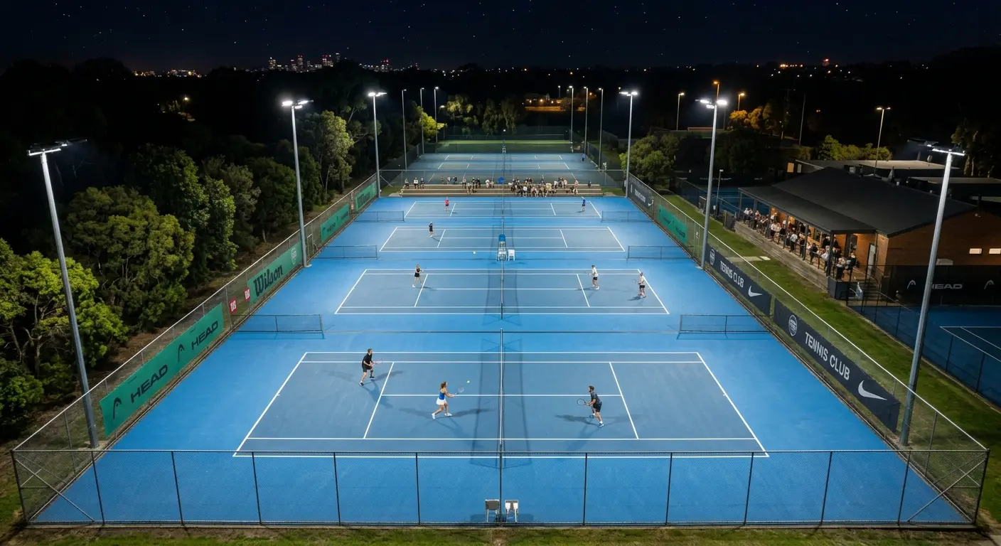
 Elite tennis court illuminated with perfect uniformity for consistent ball tracking.
When bidding on commercial athletic developments, municipal developers and EPC contracting firms often focus on raw luminous output (lumens) as the primary benchmark. However, designing high-performance tennis court lights requires a shift in perspective. Swapping precision optical engineering for brute-force brightness deforms the visual field, leading to failed inspections and poor playability.
Achieving high-grade horizontal uniformity across the court is the single most critical factor for tennis. Because tennis involves tracking a tiny ball moving at velocities up to 200 km/h, uneven distribution causes visual trajectory deceptions that disrupt competitive play.
In this engineering guide, we examine the physics of uniformity, analyze international tennis court standards (JGJ and EN), and detail how partnering with an expert sports lighting manufacturer safe guards your project handover.
1. Biophysics of Ball Tracking: Why Brightness Fails
In tennis court development, raw luminous output is only half the equation. Perfect uniformity is the determining factor of physical safety and athletic performance.
1.1 Ball Velocity and Pupil Delay
Tennis involves tracking a yellow-green optic felt ball measuring only 6.7 cm in diameter, often traveling at velocities exceeding 200 km/h (55 m/s). When a ball travels across a court illuminated by non-uniform floodlights, it passes through alternating "hot spots" (intense light) and "cold zones" (shadows).
As the ball crosses these light-and-dark boundaries, the human eye suffers from pupil accommodation delay. The iris cannot dilate or constrict rapidly enough to adjust to the shifting lumens, causing the ball to seem to "stutter" or jump in mid-air. This optical lag directly results in late swings and poor strike timing.
1.2 Visual Adaptation and Strobe Effects
When an athlete moves rapidly across the court, their eyes undergo constant transient adaptation. If the ratio of minimum illuminance to maximum illuminance is too low, the player experiences a localized strobe effect. Symmetrical reflector systems focus excessive light at the center net, leaving baseline corners in relative darkness. High-performance projects require asymmetric light curves to balance the ratios, ensuring players can track court depth and ball motion seamlessly.
1.3 Spectrum Optimization: CCT and R9
The spectral reflectance of standard yellow tennis balls peaks at approximately 555nm (yellow-green spectrum). To maximize visual contrast against typical blue or green acrylic court surfaces, the light source must offer high color fidelity.
A professional sports LED system must be configured to 5000K or 5700K natural color temperature with a General Color Rendering Index (Ra) ≥ 90. Furthermore, the saturated red rendering index (R9) must be ≥ 50 and R14 (natural leaf green) ≥ 80 to prevent chromatic flattening, allowing players to calculate court margins and ball spin instantaneously.
2. Photometric Standards & Metrics
 Point-by-point photometric grid illustrating JGJ Class I compliance.
To pass a final on-site project commissioning audit, the photometric layout must comply strictly with class-specific tiers.
2.1 Uniformity Ratios (U1 and U2)
Under EN 12193 and JGJ 153-2016 standards, sports lighting classifications dictate rigorous lux and uniformity thresholds:
Class I (Elite Professional / HDTV Broadcast): Maintained horizontal illuminance of ≥ 500 lux, with a horizontal uniformity ratio U1 (Emin / Eavg) of ≥ 0.70 and U2 (Emin / Emax) of ≥ 0.50.
Class II (Collegiate / Advanced Club): Maintained horizontal illuminance of ≥ 300 lux, with a horizontal uniformity ratio U1 (Emin / Eavg) of ≥ 0.70 and U2 of ≥ 0.50.
Class III (Recreational / Training): Maintained horizontal illuminance of ≥ 200 lux, with a horizontal uniformity ratio U1 (Emin / Eavg) of ≥ 0.60.
2.2 Glare Rating (GR) Limits
Unlike flat-plane field sports, tennis players look directly skyward during serves and smashes. Improperly angled, high-lumen floodlights project high-angle glare directly into the eyes, making the court unplayable. The GR Glare Rating must be kept under 50 (under 40 for Class I stadiums), requiring specialized sports lenses that cut off stray light beyond critical angles.
2.3 Maintenance Factor (LLF)
When calculating uniformity, many engineers make the mistake of using initial parameters. Over years of outdoor operation, dust, salt-spray, and temperature cycling degrade lumen output (Lumen Depreciation) and soil the lenses (Luminaires Dirt Depreciation).
Professional designs must apply a Light Loss Factor (LLF) of 0.80 or 0.85 (based on L90B10 thermal decay statistics). This guarantees that even after years of operation, the court continues to pass its compliance uniformity thresholds.
3. Layout Geometry & Asymmetric Beam Structuring
 A 3D CAD schematic of a 6-pole layout with asymmetric forward-throw optics.
Executing a successful tennis facility bidding project requires precise structural and physical calculation.
3.1 4-Pole vs. 6-Pole Layouts
Towers must be positioned strictly within optimal zones to control glare.
4-Pole Layout (Standard): Four poles (usually 8m to 10m high) are located parallel to the side alleys, positioned on the extension lines of the baselines. This layout concentrates light on the main playing areas while preventing direct glare behind the server's baseline.
6-Pole Layout (Championship/Broadcasting): Adds two additional poles at the net-line extensions. By dividing the total lumen output across six sources, the angles of incidence are highly balanced, producing excellent horizontal and vertical uniformity ratios across the entire court volume.
3.2 Asymmetric Batwing Optics
Symmetrical floodlights require significant upward tilting, causing heavy light pollution and high glare values. Advanced tennis configurations integrate asymmetric batwing optic modules (Type IV or Type V forward-throw lenses). This bends the light forward internally, projecting a uniform beam across the playing surface while keeping the physical lamp face parallel to the ground (zero-tilt).
3.3 Multi-Court Spill Light Control
When tennis courts are built in side-by-side configurations, managing spill light is a major engineering hurdle. Symmetrical lights bleed across courts, causing light trespass.
By selecting fixtures with sharp cutoff optics and utilizing shared-pole arrangements with asymmetric distributions, contractors can isolate illumination within individual playing margins, keeping spill light below municipal environmental standards.
4. DIALux Simulation & Design Verification
Before finalizing equipment specifications, EPCs should request a comprehensive DIALux lighting simulation. This 3D mapping models pole spacing, height, and target light footprints, validating Eh average, Eh uniformity, and GR glare ratings before physical installation. Providing this data de-risks your project and guarantees municipal compliance.
5. Conclusion
A premium tennis facility demands visual accuracy and player comfort. Simply prioritizing raw brightness over optical uniformity leads to failed audits, baseline shadows, and blinding glare. By selecting advanced asymmetric tennis luminaires and verifying configurations through detailed DIALux simulations, international EPC contractors can secure high-value contracts and deliver sports environments that meet the most demanding requirements.
Core Keywords: tennis court lights, sports lighting manufacturer, asymmetric optical design, GR Glare Rating, DIALux lighting simulation, sports lighting supplier, LED Stadium Light